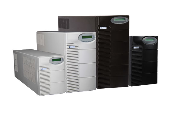
UL2 and UL3 UPS Series
- One of the most advanced and robust UPSs in the world today
- Designed to supply various types of single‐phase appliances
- Premium quality with over 250,000 hours of MTBF ( Mean Time Between Failures)
- Compliance with the global standard IEC62040‐3
- Ultra high efficiency resulting in minimum energy consumption, reduced operational cost and superb ROI
- UL3 series designed for high start‐up currents, suitable for reactive appliances such as induction loads and switch‐mode power supplies
Technical Specifications
|
General |
|||||||
| Model | UL2,UL3‐
2000 |
UL2,UL3‐
3000 |
UL2‐5000 | UL2,UL3‐
6000 |
UL2‐8000 | UL2‐10000 | |
| Rated power (VA/W) | 2000/
1600 |
3000/
2400 |
5000/
4000 |
6000/
4800 |
8000/
6400 |
10000/
8000 |
|
|
Efficiency (%) |
>98 | ||||||
| Applicable standards | IEC62040‐3 | ||||||
| Dimensions (WxDxH) (mm) | 192x480x280 | 192x530x350 | 193x673x508 | ||||
| Weight (kg) | 25.5 | 32 | 39 | 49 | 67 | 80 | |
|
Environmental |
|||||||
|
Storage temperature (°C) |
‐20 to 70 | ||||||
| Operating temperature (°C) | 0 to 40 | ||||||
| Altitude (m) | ≤3000 | ||||||
| Humidity (%) | 0 to 95% non‐condensing | ||||||
| Degree of protection against hazards and water ingress (IP) | IP20 | ||||||
| Acoustic noise at 1m (dBA) | <50 | ||||||
|
Input |
|||||||
| Phases request | 1 | ||||||
| Rated voltage (Vac) | 220 | ||||||
| Maximum input voltage in stored energy mode (Vac) | 440 | ||||||
| Maximum input voltage in normal mode (Vac) | 255 | ||||||
| Minimum acceptable input voltage in normal mode and nominal load (Vac) | 165 | ||||||
| Frequency range (Hz) | 50±5% (±1% to ±6% Adjustable) | ||||||
| Current THDi | Same as the load | ||||||
| Input power factor at normal mode and nominal load | Same as the load | ||||||
| Generator compatibility | Generator must provide UPS input power based on maximum start‐up plus battery charging power | ||||||
|
Inverter’s Electrical Output Specifications |
|||||||
| Output phases available | 1 | ||||||
| Output wave | sine wave | ||||||
| Rated voltage (Vac) | 220 | ||||||
| Voltage regulation (%) | ±1 | ||||||
| Output frequency (Hz) | 50 | ||||||
| Output frequency (Hz) | 50 ±0.0001 (Free running) | ||||||
| Acceptable input frequency for output synchronization (Hz) | 50±5% (±1% to ±6% Adjustable) | ||||||
| Max sync phase error (Degrees) | 6 | ||||||
| Apparent power (VA) | 2000 | 3000 | 5000 | 6000 | 8000 | 10000 | |
| Active power in linear load (W) | 1600 | 2400 | 4000 | 4800 | 6400 | 8000 | |
| Active power in non‐linear reference load (W) | 1600 | 2400 | 4000 | 4800 | 6400 | 8000 | |
| Start‐up current capacity (%) | 200,300 | 200,400 | 200 | 200,300 | 200 | 200 | |
| Overload (%) | 120%@100Sec. | ||||||
| THD (%)
linear load non‐linear load |
<3 <5 |
||||||
| Power factor (lead to lag) | Unlimited | ||||||
| Max output voltage variation from no load to nominal load or changing UPS operation mode (%) | <10 | ||||||
| Recovery time from start of changes to 90% output correction (mS) | <3 | ||||||
|
Battery and Charger |
|||||||
| Normal voltage (Vdc) | 48 | ||||||
| Battery type | All types of lead acid and gel, sealed or vented | ||||||
| Battery installation | External battery | ||||||
| Capability to add more packs or Battery Ah | Yes | ||||||
| Max allowed battery capacity to complete recharge under 12 hours (Ah) | 100 | 150 | 250 | 300 | 350 | 400 | |
| Charger type | Standard charger technology DIN‐41773 | ||||||
| Capability to adjust recharge current according to number of battery packs and Ah | Yes | ||||||
| Float and boost charging method | Yes | ||||||
| Maximum adjustable battery recharge current (A) | 10 | 15 | 25 | 30 | 35 | 40 | |
| Minimum adjustable battery recharge current (A) | 2.5 | 3 | 6 | 7.5 | 10 | 12 | |
| Minimum time required to recharge battery to 90% nominal capacity (h) | 4 | ||||||
| SCM recharge method | Yes | ||||||
| Capability to automatically adjust current or charger voltage | Yes | ||||||
|
Life |
|||||||
| Mean Time Between Failures (MTBF) (h) | 250,000 | ||||||
| Temperature of input electrolytic capacitors of the inverter (°C)
ambient temperature 20°C ambient temperature 40°C |
25 45 |
||||||
| Percentage of overall time when fans are turned on in nominal load (%) | <1 | ||||||
|
Isolation |
|||||||
| Magnetic isolation by iron core between AC and DC | Yes
(Transformer Based) |
||||||
| Material of winding in isolated transformer | 100% copper winding | ||||||
| Isolation class | F | ||||||
|
Protections |
|||||||
|
AC input overcurrent |
|||||||
|
Against 2‐phase in input without interruption in UPS operation |
|||||||
|
Against voltage transient |
|||||||
|
Against decrease and increase in output voltage |
|||||||
|
Against positive feedback (short between output and input) |
|||||||
|
Against output connection to the mains |
|||||||
|
Against overload and overheat |
|||||||
|
Against disconnecting the battery without disconnecting the output to replace batteries during operation and against unexpected situations |
|||||||
|
Against connecting reverse battery poles when UPS is off |
|||||||
|
Against connecting reverse battery poles while replacing, when the UPS is working, without shutting down the output |
|||||||
|
Against high input impedance |
|||||||
|
Against increase or decrease of the DC voltage |
|||||||
|
Protected charger against short circuit |
|||||||
|
Against improper quantity of connected batteries |
|||||||
|
Against output short circuit |
|||||||
|
Earth protection |
|||||||
|
Input and output protection against RFI and EMI noises |
|||||||
|
Computer network protection (Ethernet) against transient voltage (Spike) with 1500W power |
|||||||
|
Information Transfer Connectors |
|||||||
|
RS232 Serial port |
|||||||
|
Serial port to LAN converter (optional) |
|||||||
|
GSM modem (optional) |
|||||||
|
Free‐contact relays (optional) |
|||||||
|
Remote control LCD panel (optional) |
|||||||
|
Screen and Alarms |
|||||||
|
LED screen |
|||||||
|
Capability to change settings by LCD |
|||||||
|
Audio alarms |
|||||||
|
Speech warnings (optional) |
|||||||
|
Other Capabilities |
|||||||
|
Modular internal powers with 1 and 2 kVA power in parallel redundant configuration (A possible error in any of the power modules would cause the output power to reduce 1 or 2 kVA and it would not damage the device) |
|||||||
|
UPS installation as a shared neutral |
|||||||
|
Software with UPS monitoring capability |
|||||||
|
Software with management and configuration setting capability |
|||||||
|
Software with capability to record the operation and failure reports |
|||||||
|
Software with capability to monitor multiple UPSes simultaneously (optional) |
|||||||